How to start in FPGA development? - Some tips
Introduction
The aim of this tutorial is to show some useful tips for people like me that one day started from zero to work with FPGA's. Why FPGA's? Because they are easy to use and they are not too expensive, and they are usually used in lab courses to let students "play" with them.
1: How to choose the right FPGA?
As you may know there are a lot of different FPGA's, brands and models. How to choose the right one? It's very difficult to say that before knowing which will be the system implemented in it. It depends on the characteristics of the description, the specs of your design, the developer desires.
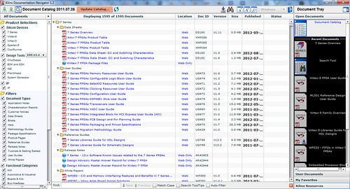
For example, I'm a Xilinx fan for several reasons. One of them is that the documentation is always easy to find and is very well organized on the support webpage. Every FPGA has the same datasheet structure and it's very fast to find the important information for your design, and also compare with different models in the same family with the Family Overview datasheet. There is still something more interesting to get the information, the Documentation Navigator! (You can follow this link to download it; you have only to write your registration Xilinx ID) It's an application that you can install to your computer and have the updated documentation for each Xilinx FPGA, there is no need to download each infinite pdf's to find what you are looking for, there is even a search tool. Another reason is because, even if the interface is not for free, the Xilinx ISE it's very intuitive, it's easy to know how to use the basic tools.
So, as a result, if you want to know which is the best FPGA, first think about the needs of your design and which your desires are; after that? Check the prices and choose the one you can afford.
2: How do I start my design?
Start a design from zero is not a trivial issue. There are a lot of things that you have to take care of and think about. Even after designing all the architecture you'll find some parts that don't work in the way that you have designed, and you'll have to go back again and redesign.
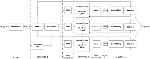
First of all maybe one of my first advices will be to draw a flow diagram, it could sound silly, but it's very useful. This helps you to define your data flow, where do you need to register your data, the data size. You don't have to do it in a very low level, the image below shows one possible example.
You can also do it in a lower level, and specify more the data size or the equation or functions that had to be done.
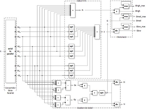
It's interesting to find out which is the bottle neck path and try to think the way to optimize it before to start coding. You can always do it afterwards, but it's better to think about it at the beginning.
The next step is to translate those schemes to VHDL code. I suggest you to write your code in MATLAB, C or some script language that you actually know. This will help you to organize the structure of the code and to be sure that what you want to implement really works. And remember that anything that can be written in MATLAB or C can be written in VHDL.
3: Entity levels
Start the code from zero has one advantage and one disadvantage. The first one is that you can write your code with your own style. The second one is that you find yourself in front of a white "paper";. The importance of the high level flow diagram is that helps you to organize your entities. If it's the first time that you start a big design, will be helpful if you write the code for the top level entity: the inputs and outputs, the instantiation of the entities that are enclosed and the module implementation. You can follow this hierarchy with all the other entities. In my opinion, don't try to put a lot of hierarchy levels; it could make the code too messy.
4: The functions
I don't know you, but when I was at the university they forgot to tell me that there was something called functions. When you are used to code in C or MATLAB, functions are the basis to compact code and make it readable. Functions in VHDL work more or less in the same declaration way, but something is missing; they are only allowed to have one output. Here below you have an example of how the function max could be implemented:
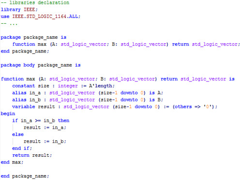
They can be used to substitute some entities that have only one output. They are easier to instantiate, like MATLAB or C do, but you have to think that they are not programming language functions. As I told before, yes you can write in a hardware description language what is written in a programming language, but you have to remember that they are not the same. It means that when a function in HDL is called, a dedicated hardware is synthesized, so if you call a function 5 times it is the same as instantiating an entity 5 times. Functions can either be written into a process or combinational way.
Also you have to remember that a programming language is executed in an exclusive way: sequential and it follows a time line during the execution. On the other hand a hardware description language allows both concurrent and sequential execution. So the call of the function on the line x will not be done before the one on the line x+1, but at the same time.
Finally, during the debugging process you'll find out that variables declared in a function are not able to scope. I advise you to write the code using entities and after being sure that your code works, rewrite them as functions if you need. Or simply simulate each function separately before call it from an upper entity.
5: Debugging time
The worst or the best part when you write your own design is the simulation/debugging part. Before simulating I expect that you had compiled and the code is well written, no syntax mistakes. The best and most relieving part comes when you simulate your design and the results are the ones expected. Then the description part is finished and you can move to the next step, the implementation into the FPGA.
However, if the first simulation fails, you must start your debugger mode. The first step is to write a good test bench or test file (.do). Which one is better? It depends on your own. In some cases I'll prefer the .do files because they are easy to write, edit and execute, mostly if you use ModelSim for simulations. In my opinion it seems that .do files are more for people that believe in: get things done. But .do files are not as "nice" as test benches are.
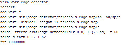
Below you can find a basic example of how to take advantage of the .do files. The first line calls the simulation of the entity you want to test. I think it's always useful to restart the simulation. But you have to take in consideration that this will erase all the signals you already have in the wave window (from ModelSim). You can add to the simulation all the signals you desire. In that case all the input and output signals from the entity edge_detector (add wave *) and the ones from the sub entities sp and threshold_edge_map. It's also allowed to add dividers, which is useful to differentiate between blocs of signals. And the force command generates the impulse for the simulation. The last statement must be the run, which determines how many time will the simulations be running. After the run command if you add more signals, those ones will not be simulate. You'll have to restart the simulation again to add them.
This is a very basic introduction about designing with FPGA's; there are a lot of things missing. But I hope this will be the beginning of a series of posts with some basic information about how to start.
- Comments
- Write a Comment Select to add a comment


Hi Nuriaorduna,
I'm totally newbie to this. I'd like to learn about FPGA. Kindly point me to direction to start learning and coding this.
I'm good at C programming and I have some working experience in UEFI also.
-Prem.
To post reply to a comment, click on the 'reply' button attached to each comment. To post a new comment (not a reply to a comment) check out the 'Write a Comment' tab at the top of the comments.
Please login (on the right) if you already have an account on this platform.
Otherwise, please use this form to register (free) an join one of the largest online community for Electrical/Embedded/DSP/FPGA/ML engineers:


